GPS Antenna Signatures
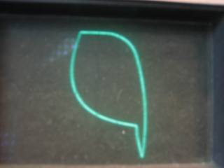
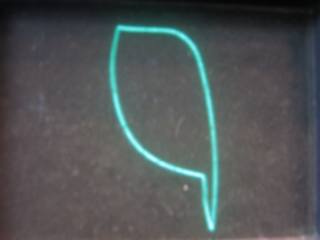
A handy way to characterize components is with a power signature. This is done by stimulating two points (usually a node and ground) with an a.c. test signal. When voltage is plotted on the X axis of an oscilloscope and current is plotted on the Y axis an unique signature results. The test signal is a triangle wave with just enough amplitude to bias a transistor. The following signatures are of GPS antennae.
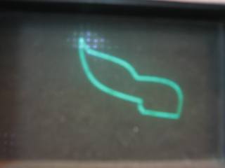
S/N 6366
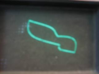
S/N 5049
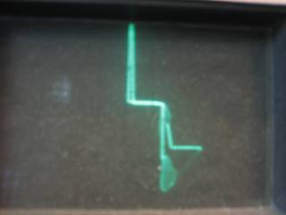
SN: NPM02500030

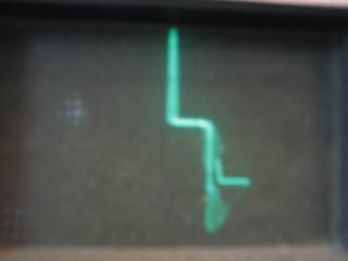
S/N SM16220 (GPS 1)
S/N (GPS3)
S/N GC16629